| Contact Us |
| Home |
| Pump Parts & Manufacturers List |
| Testimonials |
| About Us |
| Linecard |
| Agitators & Mixers |
| Air Compressor & Vacuum Process Systems |
| Accessories |
| Brewery Equipment |
| Chemical Feed Systems |
| Heat Transfer Products |
| Macerators |
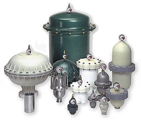
| Pulsation Dampeners |
| Pulsation Dampeners |
| Operation & Applications |
| Plastic Pulsation Dampeners |
| Metal Pulsation Dampeners |
| Sanitary Pulsation Dampeners |
| Teflon Pulsation Dampeners |
| High-Pressure Dampeners |
| Sanitary CIP |
| Options |
| Surge Suppressors |
| Suction Stabilizers |
| Thermal Expansion Chambers |
| Isolation Diaphragm Seals |
| Leak Containment Systems |
| Controlling Surge & Pulsation Article |
| Pumps & Accessories |
| Pump Repairs & Parts |
| Separators |
| Shear Blenders & Pumps |
| Tanks |
Sales & Service Locations: Austin, TX Corporate Offices: 1170 Tree Swallow Drive |
|
Controlling Surge and Pulsation Problems
The plant may be imaginary, but the problems are real. Take the tour and learn the most common causes of problems like water hammer, and how you can prevent them by Gary Cornell, Blacoh Fluid Control There was no mistaking the sound – that rushing metallic thud. As the valve slammed shut a pressure wave travelling at 4000 feet per second and more than five times normal system pressure instantly crashed into the one-way check valve protecting the main supply pump from back flow. Once again, the integrity of the system held, but everyone knew it was just a matter of time. This article addresses the all too common scenario of working near pumping systems that are on the edge of catastrophe. The causes, results, and solutions to the problem of surge or "water hammer" will be discussed, as will the different but related problem of pump-induced pulsation. To look at the practical side of surge and pulsation, we will take a trip through an imaginary, but realistically depicted modern manufacturing plant. To set the stage for our tour, we need to describe hydraulic conditions that set up the potential for these problems to occur. Both surge and pulsation in a liquid handling system are the result of uncontrolled pressure waves caused by an abrupt change in flow, either directional or volumetric. Liquids contained in an enclosed system (piping) have a physical volume; therefore, a mass can be measured and/or calculated. We can then determine acceleration forces needed to move that given mass. Once in motion, the mass will stay in motion as long as enough force is applied to overcome friction loss plus any gravitational component. It can be said that hydraulic equilibrium is reached when the fluid is flowing in a laminar state. Since for all practical purposes liquids are not compressible, force or energy is not absorbed into the fluid but rather is transferred through it. The kinetic energy of the moving fluid will exert all the force it has acquired to resist any condition that tries to cause a change in its velocity. Depending upon the mass and velocity of the liquid and rate of change applied to it, very destructive forces can be generated leading to catastrophic component or system failure. The critical consideration for this discussion becomes the rate of change in energy for any given mass. For example, consider the analogy of a battleship moving at full speed. If the engines were stopped, the ship will travel about five miles bleeding off the kinetic energy through water friction before coming to a stop. No damage would be incurred because the massive amount of energy involved is allowed to change form slowly. However, if that same ship at full speed were to run squarely into an aircraft carrier, all the kinetic energy would be concentrated and would change form very rapidly – in a matter of seconds. Since the greater mass of the carrier could not absorb the kinetic energy as fast as it was being delivered, the energy would become concentrated at the point of impact. In liquid transfer systems, kinetic energy is generally observed as pressure. Therefore when fluid velocity is changed, the result is an increase or decrease in pressure. Commonly, changes in velocity occur when pumps are started or stopped (either intentionally or due to failure), fluid flow direction changes abruptly, pipe diameters change abruptly or a quick-closing valve closes. SurgeAt least in potential, a quick-closing valve (generally one that closes in less than 1.5 seconds) represents the most dangerous condition. Since liquid efficiently transfers energy rather than absorbing it, a sonic or pressure wave is created. The intensity of the pressure shock wave is directly proportional to the speed of flow before the change in velocity and to the speed of propagation of the sonic wave created. Unrestricted, the pressure spike in the liquid will rapidly reach the speed of sound moving through liquid (approximately 4700 feet per second). This is more than four times the speed of sound through air. It is mathematically possible to calculate this pressure increase. For design purposes, the increase in pressure can be determined by the rule-of-thumb formula: P = 60 × VS Where: P = The increase in pressure over the steady-state system flowing pressure For example, consider a 2" pipe carrying 60 gallons per minute, with a system pressure of 100 psi and a specific gravity of 1.2, and a valve closing in one second. The 2" pipe and gpm equates to a flow rate of 6 feet per second. In this scenario, the pressure increase above normal flowing pressure would be 432 psi, creating a total spike pressure of 532 psi. If the valve were shut in half a second, the peak pressure would double to 1064 psi. Conversely, if the valve were closed in 2 seconds, the peak total pressure would be half of 532 psi, or 266 psi. Note that the pressure increase is independent of, but cumulative with, the normal system pressure. For example, a system pressure of 50 psi flowing at 10 feet per second would have the same pressure rise for a given rate of change in velocity as a system pressure of 300 psi flowing at 10 feet per second. The proportional pressure change, however, would be a much higher percentage. Therefore, regardless of whether it is low or high pressure, the system may not be able to handle the pressure wave. Clearly, when a mass such as liquid in a pipe is in motion and its velocity is changed, there is the potential for a catastrophe. PulsationUnlike surge, pulsation is the rapid uncontrolled acceleration and deceleration of units of energy. In the context of this article, these units of uncontrolled energy are actually slugs of liquid moving through a pipe. The degree of pulsation in them is usually designated by frequency in Hertz and a pressure amplitude. Outwardly, pulsation is usually observed as component vibration or rapid gauge fluctuation. On an oscilloscope it appears as a sinusoidal curve (waves of peaks and valleys). Pulsation can occur and/or be influenced by the specific harmonics of various components in a liquid transfer system. Piping, valves and mechanical movement – and system design itself, to a certain degree – combine to influence measurable vibration. However, the system component that instigates the pulse generation is the pump – specifically, a reciprocating. positive displacement pump. This type of pump creates its motive force by repeatedly capturing and expelling a predetermined slug or volume of liquid. It does this by using inlet and outlet valves, which account for rapid acceleration and deceleration of fluid. Pulsation, then, is a rapidly repeating change in energy form. Depending upon its frequency and amplitude, the potential for catastrophic system component failure is very real. A simplistic comparison would be to the weakening effect of the human arterial system caused by a constant elevation in heart rate and blood pressure. The major pulse in a pumping system will be at the frequency of the plunger or piston speed times any multiplicity factor. By way of reference, a reciprocating pump's pulsation is generally described as high amplitude, but low frequency, as compared to the high frequency but low amplitude of a centrifugal pump's impeller vanes. Seldom are liquid handling systems designed with an analysis of the total system harmonics that will occur. Whenever a reciprocating pump is called for, at the very least, consideration must be given to the potential effect of the pulsation generated. In most cases, minimizing pump-generated pulsations will provide sufficient system protection. However, if the need is to eliminate total system vibration, rather than pump-generated pulsations, then both system and pump harmonics must be considered. In such cases, if there happens to be a harmonic match of frequencies, pressure amplification can be many multiples of that generated by the pump alone. This is more likely to occur at higher frequencies such as those generated by a centrifugal or multipiston pump. The TourNow that we have explained fluid movement and discussed the undesirable effects that changing dynamics can produce, it is time to visit our imaginary plant. For our tour we have selected the Quality Paint Company. QPC is one of the largest paint manufacturers in the United States, with eight plants located from coast to coast. They specialize in water soluble paints using state of the art manufacturing equipment. Stop 1: Tank Farm Transfer PumpsAs we pass the guard shack, the first thing we notice is a tank farm. QPC purchases titanium dioxide (TiO2) solution in bulk and stores it in eight 10,000 gallon tanks. The TiO2 is transferred into the facility as demand requires. For several reasons, including the abrasive nature of the material, the sheer sensitivity and operational characteristics required, the transfer pumps are air operated double diaphragm (AODD) units. Each tank has its own pump supplying product to a common header pipe going overhead into the plant. Even though AODD pumps are the best choice for this application, they have a rather poor tolerance for high inlet pressure. When the inlet pressure approaches 12 to 16 psi, pump diaphragm life starts to deteriorate rapidly. Since QPC's TiO2 tanks are 30 feet tall and their particular mixture has a specific gravity of 1.3, the static inlet pressure is 16.8 psi. (height in feet × .432 × 1.3 s.g.) AODD pumps are positive displacement, so they have inlet valve balls that act exactly like quick-closing valves. From our previous discussion we know that quick-closing valves create instantaneous pressure spikes several times higher than flowing pressure. Since 16.8 psi is above the pump manufacturer's maximum allowable inlet pressure, we can predict that there will be problems. What happens in the pump is pretty straightforward. The spike created when the inlet valve balls dose on the liquid chamber seeks to move to a lower pressure area. Since the inlet valve on the pump's other chamber is simultaneously opening and the motive diaphragm is creating a vacuum, this becomes the low pressure area. The pressure spike rushes in and slams against the diaphragm. This distorts and stresses the diaphragm, leading to premature failure. PositioningWe see that the pump is located at the bottom of and just two feet or so away from the tank. Because it is this close to the tank, acceleration head is not a significant factor. One method of reducing high inlet pressure is to reduce the height of the tank, but this is not practical here. The AODD pump has several features that make it the best choice for this application. So what can be done? A practical and economical solution is to install an inlet stabilizer as close to the pump's inlet as possible, but within 10 pipe diameters. Inlet FactorsAn inlet stabilizer is a hydro-pneumatic device consisting of a pressure vessel with an elastomeric bladder or diaphragm inside it that separates a compressed gas charge from the liquid being pumped. The inlet stabilizer literally acts like a shock absorber and receives the pressure spike created when the pump's inlet valve closes. An inlet stabilizer is typically precharged to 50% of the static inlet pressure. When properly charged and sized, it will minimize the stress on the pump's diaphragms by temporarily accumulating liquid and absorbing the pressure spike. This minimizes stress on the pump's diaphragms. Discharge FactorsNow that the pump has been protected, the discharge needs to be examined. The AODD pump produces a pulsating flow. As previously mentioned, pulsation is the rapid acceleration and deceleration of liquid caused by the reciprocating action of the positive displacement pump in conjunction with the quick opening and closing of the pump's discharge valves. This pulsing flow will be observed as pipe vibration as energy rapidly changes form. Vibration Concerns – Mechanical and LiquidThere is also mechanical vibration caused by the shifting of pump components. And remember, if both mechanical and hydraulic pulses coincide, vibration will be increased by a multiple factor. Due to the overhead piping configuration, vibration is a serious problem. There are several ways to minimize the hazards caused by this vibration. Larger diameter pipe can be used to reduce back pressure. Thick wall pipe can be installed to delay the eventual pipe fatigue. Pipe braces (not hangers), used for support, can absorb some of the vibration. In effect, the system can be overbuilt to absorb and disperse the vibration caused by pulsation. Back pressure valves and orifices can provide some dampening effect but usually at the expense of efficiency. All of these solutions, however, simply address only the symptoms of the pump vibration and pulsation. They will be costly and only delay inevitable component and/or system failure. The most economical and proper way to minimize a pump's mechanical vibration is to use some type of flex coupling between the pump and the discharge pipe. This isolates the system and prevents component damage. Several companies supply this product. Sometimes, however, all that is required is a length of hose reinforced to withstand system pressure. As a rule of thumb, the hose should be at least 15 pipe diameters long. The most economical and efficient way to dampen the liquid's hydraulic pulses is probably a pulsation dampener. This device is similar in construction to the inlet stabilizer, but it must be pressurized to 80% of the liquid flowing pressure. The pulsation dampener will absorb the spike created by the rapid acceleration of the liquid during the discharge stroke of the pump. At the same time it will accumulate a small amount of the liquid. When the pump shifts, pressure is momentarily reduced as discharge volume is lost and the dampener releases accumulated fluid back into the pipeline, filling the void created during the pump shift. Thus will minimize vibration. Also, liquid flow downstream of the dampener will now be in a continuous steady state rather than a pulsating start/stop mode. Stop 2: From Mixing Tanks to BlendersAs we continue our tour and enter the plant, we see large mixing tanks where the paint is blended. Since the main ingredient in water based paint is water, we see an 8" water line running overhead for the length of the plant. Coming off this main header are six 4" branch lines, one to each blending tank. Following the main line back, we observe that the water flow is produced from a holding tank by an 8" end suction centrifugal pump producing 1500 gpm at 180 feet of head. A one-way stop check valve prevents system back flow, protecting the centrifugal pump and creating a pressure tight seal. The centrifugal pump starts on demand. The demand is based upon pressure changes in the system when valves at the blending tanks open. These valves must be quick closing type because when a predetermined weight of water is let into the blending tanks flow must immediately stop. From our earlier discussion on surge or "water hammer," we know that as a mass changes velocity, there is the potential for rapid energy transformation. In this water feed system, we are faced with the following potential problems:
Although there can be other design factors of the system that either minimize or exacerbate such hydraulic problems, the items above represent the greatest potential for disaster. Rapid Pump StartQPC's centrifugal pump will start automatically when the system pressure drops due to the opening of a blending tank's valve. When this occurs, the pump will throw water into the 8" pipeline that is filled with a stationary water column. As the rapidly moving water collides with the stationary column, a pressure (energy) spike will occur. This is similar to an automobile running into a block wall. Great stress will be put on the system. To prevent this from happening, several options can be considered: Slow or soft start pump motors will introduce water into the system slowly and minimize the pressure spike. This is a costly but effective solution. Slow opening isolation valves will be closed when the pump starts up. They will open slowly, allowing gradual pressure increases as flow increases. Pressure will slowly increase to equalize the force of the stationary column of water. This solution can be complicated and expensive from a control point of view, but it will minimize the pressure spike. Surge tanks are closed vessels with air trapped in them. When the pump is started, initial water flow will enter the surge tank until system pressure is equalized. The surge tank's major drawback is that the air trapped in it will be absorbed, creating aerated fluid which is undesirable in paint products. In addition, once a waterlogged condition exists, all cushioning effect will be lost. Surge suppressors are similar in design to surge tanks, but there is an elastomeric bladder inside separating the fluid from a compressed gas charge. By capturing the gas charge, the proper pressure required for the specific application can be maintained. The suppressor should be charged to approximately 85% of normal operating pressure. A surge suppressor is an effective and cost-efficient way to minimize the pressure spike that occurs during pump start up. Rapid Pump ShutdownWhen the pump is turned off, the flow at the pump's discharge stops quickly. This creates a low pressure area. Fluid column separation can occur as momentum temporarily continues to move the mass of water down the pipeline. As soon as friction acts to slow the forward motion of the liquid column, it will reverse and travel back toward the low pressure area at the pump discharge. The reversal will travel at the same speed as its initial forward motion. Depending upon the initial flow rate, the pipe gradient and the fluid mass, the pump casing will be stressed, with a potential for failure. Also, pump seal integrity can be lost, and the impeller can become warped. Additionally, systems with a check valve can create a water hammer effect with catastrophic transient pressure spikes when the reverse flow hits the one-way check valve. There are several solutions to this problem: Controlled-close check valves can be used to time the dosing period. A dashpot device or motor control on the valve can be used to accomplish this. If we control the rate of change in the velocity of flow, we can minimize the amplitude of the pressure spike. This type of control valve works well in conjunction with check valves, but they must be maintained for reliability, and they can be an expensive option. Surge Suppressors can be installed just downstream of the check valve or, if no check valve is used, at the pump discharge. Properly sized and precharged to 50% of operating pressure, a surge suppressor will accomplish two things. First, being pre-charged to 50%, the vessel will accumulate fluid during pump operation, and this accumulation will be released at shutdown to prevent column separation. Second, the suppressor will absorb the pressure spike generated as the water column reverses against the check valve or pump. The suppressor is a straightforward and economical approach. Pump motor failure or loss of power is another contingency that must be considered. While modern electric pump motors are extremely reliable, failures do occur. Power outages and surges must also be taken into account. When the motor stops, the same condition exists as at pump shutdown. That is to say, column separation can occur and now will reverse against the check valve. The worst possible situation is where power is only momentarily interrupted and then, just as the flow column is returning to the pump, the pump restarts. This would be similar to a head on collision of two automobiles travelling at high speed. Options to control these situations are few. Certainly an interrupt or time delay switch could be installed at the motor to prevent an immediate automatic restart. Controlled close and open check valves will not be an option because they probably would not be operable or would not react fast enough. The best choice here would be a surge suppressor. The compressibility of the gas in the suppressor will react instantly to the transient pressure spike. Quick-Closing ValvesMoving down the water feed line, we now need to determine what will occur when the valves at the blending tanks are closed quickly. For purposes of this discussion, we will define a quick-closing valve as one that shuts in 1.5 seconds or less. It is important to remember, however, that as valves get larger, they can still cause problems even if they close slowly. But what actually occurs to create a potentially catastrophic spike? When one of the valves doses quickly, fluid flow is instantly stopped, but the column of water behind it will still be moving. Think of a speeding train with the engine abruptly hitting a stationary blockage. The engine stops, but the cars continue moving forward. The only difference between a train and water flow is that the train is not contained, and the cars derail. If the pressure spike does not rupture the pipe or some other component, the compression wave created will reverse and travel back down the pipe toward the pump at the speed of sound. When the wave hits the check valve or pump, it will again reverse and continue to reverberate until something finally breaks or the energy dissipates due to friction loss. Even if nothing fails initially, the system is under repeated stress, a situation that will ultimately lead to fatigue failure. What can be done to prevent this? The pressure spike can be either released or absorbed. The following options are among the most accepted solutions:
Rupture discs are simply plugs that will break at a lower pressure than any other component in the system. They are usually a "last resort" protection and are not normally used to control pressure spikes because the liquid released into the environment is often hazardous, costly, or just dangerous in being released at such a high pressure. Pressure relief valves are valves that will open at a predetermined pressure. As the pressure spike builds, the relief valve will open, and fluid will be released. Either a holding tank or a return pipe system must be installed to exercise this option. Valve sizing and relief pressure settings are critical to minimize a spike as quickly as possible. This approach can be costly, and relief valve reliability must be tested regularly. Slow closing valves will solve the problem if there is truly no need to close the valve quickly. Tn QPC's application, however, it is necessary to stop flow instantly, so this solution is not an option. Surge suppressors provide a solution that will absorb the pressure spike by momentarily accumulating the flow of liquid as the valve closes. Because of the speed of propagation of the transient wave created, the surge suppressor must be installed directly upstream from the quick-closing valve and in no situation further away than 10 pipe diameters. Since the full capacity of the suppressor must be available to accept the accumulation of liquid when the valve closes, the suppressor must be precharged to 95% to 98% of system pressure. It must be properly sized so that it can provide the proper compressed gas cushion and momentarily accumulate a predetermined amount of liquid. A surge suppressor installed at each quick-closing valve for this application will provide economical and reliable protection. In addition to the water supply system, we observe a bank of metering pumps that are used to inject precise amounts of fungicide into the paint blenders. This is accomplished using small single-diaphragm metering pumps dispensing the chemical through a precise mass flow meter. Because of the reciprocating nature of the metering pump, we know the discharge flow will pulsate. In many applications this is not a problem, but because the flow meter cannot accurately measure a pulsating flow, a pulsation dampener must be installed at the pump's discharge. If properly sized and charged, the dampener maintains the mean system pressure within 1%, which is sufficient for the meter to function properly. Stop 3: Packaging the Finished ProductFrom the blending tanks, AODD pumps transfer the paint to holding tanks before it goes to filling equipment. The AODD pumps are all fitted with discharge pulsation dampeners to prevent rubber hoses, which connect the pumps to the tanks, from "jumping" around the plant floor and endangering employees. Hose jumping results from pulsations created by the start and stop action of the pump. In addition, the jumping will wear holes in the reinforced hose wall as it rubs on the plant floor. Since it installed dampeners, QPC has been able to reduce hose replacement significantly. As we pass the filling equipment for buckets and cans of paint; we observe several more pulsation dampeners, again installed in conjunction with AODD pumps. The filling machines cannot be accurate with pulsating flows. The manufacturer of the filling equipment installs dampeners on its equipment, so that whether buckets and cans are filled by flow meters or by bulk weight measure, the flow is laminar and measurable by the instrumentation. The FutureThe last stop on our plant tour is the research and development area. QPC is committed to ongoing product development, and today technicians are testing a new proprietary paint for spray applications. They are using a piston type spray pump, which produces a pulsating flow. Their goal is to produce a paint that will disperse well through spray nozzles for coating purposes. They will need to use a pulsation dampener with this pump for two reasons. First, system vibration at the pump's high cycle rate can lead to fatigue and eventual system component failure. Second, without the dampener, the spray pattern produced will be wavy and inconsistent as the spray rises and falls in synchronization with the pressure pulse from the pump. The inconsistent pattern will require over-spray to coat the test board. This results in paint waste and non-uniform coverage. Properly sized and charged, a pulsation dampener can provide the required level of dampening to allow for a smooth and continuous flow from the nozzles. Although our tour is finished, there are many other pump systems in a typical plant that would benefit from pulsation and surge control. Each should be analyzed with regard to potential hazards that may result from a change in velocity of the flowing fluid or from the pulsations created by a reciprocating pump. Examples include filter press systems, where the pulsating flow from an AODD pump can damage filter media or "cake", and in-line mixers, which benefit from a steady stream of injected fluid as opposed to slugs of liquids. Our tour was not designed to be a detailed analysis of every system, but rather to highlight the kinds of damage that can occur in any system that uses pumps and valves. No manufacturing plant need subject itself to the potential hazards of pulsation and surge. I have made no attempt to explain sizing, materials or other parameters involved in using the preventive devices reviewed. In some cases, complicated mathematical formulas are required to make such determinations. There are several good manufacturers of the various devices discussed. You should consult with these manufacturers or their distributors to determine the proper product(s) for your specific application. References: Karassik, Igor, William Krutzsch and Warren Fraser. Pump Handbook. McGraw Hill (1976) Wachel, J.C. and S.M. Price. Understanding How Pulsation Dampeners Work. The American Society of Mechanical Engineers Pipeline Engineering Symposium (1988) Young, Winston. The Young Engineering Technical Manual. Young Engineering, Monrovia, CA |
|
|