

| Contact Us |
| Home |
| Pump Parts & Manufacturers List |
| Testimonials |
| About Us |
| Linecard |
| Agitators & Mixers |
| Air Compressor & Vacuum Process Systems |
| Accessories |
| Brewery Equipment |
| Chemical Feed Systems |
| Heat Transfer Products |
| Macerators |
| Pulsation Dampeners |
| Pumps & Accessories |
| Air Operated |
| Metering Pumps |
| Centrifugal |
| Sanitary "3A" Compliant |
| ZP3 Clean-In-Place |
| ZP1+ Series |
| ZP1 & ZP2 Series |
| AL Series |
| SP Series |
| AC Series |
| LC / LD Series |
| M Series |
| D Series |
| CIP Pumping |
| CIP Evolution |
| Magnetic Drive |
| Marine |
| Industrial |
| Chemical |
| Peristaltic |
| Lined |
| Vertical In-Line Multistage |
| Pump Repairs & Parts |
| Separators |
| Shear Blenders & Pumps |
| Tanks |
Sales & Service Locations: Austin, TX Corporate Offices: 1170 Tree Swallow Drive |
|
CIP Pumping Systems: Mixing the Old and New
by John H. Horwath reproduced from Pumps and Systems Magazine Pumps designed for today's clean-in-place systems are a far cry from the general purpose industrial units first introduced during the 1940s in dairies to replace what was then a totally manual process. The then new procedure employed tanks, piping, valves, spray balls and pumps. CIP systems also used more effective acid and chlorate detergent blends developed by the chemical industry. These blends improved cleaning capability immeasurably. In addition to providing a cleaner system, there was a huge cost savings since manual labor constituted as much as 50% of the total milk cost from farm pick-up to distribution of the product. In 1953 the first 3-A* Standard for CIP cleaning was published. Minimal requirements established for satisfactory application included a suggested cleaning procedure. Since its conception in the dairy industry, the basic procedure has been modified and accepted in other industries: 1960s — Food and beverage 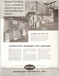 Designing a CIP process involves consideration of materials and methods of construction, specialized cleaning equipment, and processing equipment design that is conducive to CIP cleaning. A first generation permanently installed storage tank and tanker washing system is shown at right. The first CIP recirculating units were portable and generally consisted of a small tank pump, regulator and a return line recorder mounted on a dolly. Hoses connected the recirculating unit to the piping circuit or to a spray line. This permitted effective cleaning, but the labor cost saving was insignificant because the portable arrangement could not be automated. Permanently installed CIP supply return piping was an integral part of the first single automatically controlled recirculating unit. Introduced in the 1960s, this arrangement featured several important improvements:
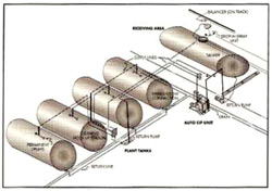 The figure at right depicts a basic arrangement of a latter-day CIP system incorporating supply/return piping for cleaning four in-plant tanks and an individual mobile tanker in a receiving area. Check valves in the system provide continuous movement of flush, wash and rinse solutions from the return pumps back to the recirculating unit. Solution supply to the sprays is controlled by one air-operated valve and a u-bend position on a cleaning hook-up station. Return flow from the tank is accomplished by installing a removeable elbow between the tank outlet valve and a permanently installed return header to the pump. Note that tankers are cleaned with a drop-in spray nozzle supplied by a hose, and the tanker return flow is through a hose to a permanently mount return pipe. The CIP PumpAs clean-in-place operations grew more sophisticated, so did the specifications governing the pumps. Interestingly, however, neither the flow requirement nor the specified head have changed in the last 40 years for the majority of services. Typically, flow rates for individual spray heads range from 5 to 200 gpm, with operating spray nozzle pressures as low as 5 psig and as high as 60 psig. A minimum flow rate of 5 ft/sec in considered desireable through most pipe lines. Cleaning agents commonly used include alkaline compounds, acidic compounds, water (hot and cold rinses), water conditioners and wetting agents (surfactants). Most dairy, food and pharmaceutical equipment can be effectively cleaned with a solution that is 99.5 to 99.75% water. Chemicals (liquid or dry form) make up the remainder. While lines are pressure washed, processing and storage vessels are sprayed with the solution generally on only the upper surfaces, with the liquid then cascading down the sides of the vessel chamber. Recirculation is essential to maintain economic operation of the high volumes of solution that must be brought into contact with the soiled surfaces for periods of time ranging from 5 minutes to 1 hour or more. Because of pressure requirements, 3500 rpm centrifugal pumps are used to deliver the cleaning and sanitizing solutions to the spray balls. Low head units running at 1750 rpm can be employed as return pumps. However, there are occasions where the higher head 3500 rpm units may also be used in return circuits. Some CIP installations utilize a gravity or eductor arrangement to return the solution back to the tank. When air-bound problems occur in return lines, modifications can usually be made in the system or pump to alleviate the condition. The Net Positive Suction Head (NPSH) available for the supply pump is a critical design consideration in a CIP suction system – particularly when CIP fluids are heated (raising their vapor pressure perceptibly) to the point that temperature can become the predominant factor in the NPSH available. To avoid suction cavitation, the system NPSH available at the highest liquid pumping temperature and lowest suction level must be equal to, or greater than, the pump's NPSH requirement at the intended point of flow. The solution contact surfaces are usually stainless steel (300 series) with surface finish dependent on how the part is manufactured. Wrought product resulting in a fabricated or stamped component has more stringent finish specifications than that of a component manufactured from an investment casting process per the 3-A standard. 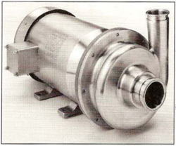 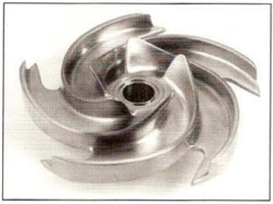 Today pump manufacturers offer a variety of designs and surface finishes for CIP pump applications, ranging from an all-cast surface finish to an all-polished surface. In between this range, pumps are available with inside polished and an outside cast surface, or the opposite – a cast inside and a polished outside to maintain uniformity of appearance in the exposed areas (as in photo at top right). Non-polished interior units can be furnished with cast enclosed impellers while polished interiors require a semi-open impellers arrangement (photo at bottom right). A vast difference in pump performance exists dependent on which manufacturing process is followed. Initially, CIP pump designs developed from wrought sheet and plate were utilized for handling both product (milk) and cleaning solutions (cleaning compounds). These fabricated units, while quite economical, delivered relatively poor overall performance – primarily because of the hydraulic design. On the other hand, cast pumps intended for handling only the cleaning solution performed well and generally lasted longer. Fabricated units were developed primarily for the dairy industry. Cast units evolved from industrial pump design and combined empirical and theoretical approaches that utilized the advantage of smooth conversion of velocity energy to pressure energy through transitional streamline conversion. Why Industrial Pump Design?Redesigned industrial style centrifugal pumps have been utilized for CIP throughout the world for more than 40 years. Why have these units been so highly accepted even as systems become more complex? Because they have the proper hydraulic design and, if operated and maintained correctly, are reliable, efficient, quiet running and long-lasting. Modern manufacturing processes have increased the performance range of CIP pumps and reduced their costs. Hydraulic DesignAs manufacturing processes improved in the 1960s and 1970s, Ampco and other manufacturers began adapting investment casting foundries and NC machining practices. Today the basic difference is not in manufacturing, but in the pump's hydraulic design. Fabricated design units cannot provide the generated transitional flow paths required for an efficient conversion of velocity energy to pressure energy. Established design concepts carried over from 50 years of the fabrication process mind set have slowed total acceptance of the intricate investment casing capability by basic fabricators. Individual components or segmented portions of their positive improvements have been made, but not one has made a total approach providing what a CIP pump should have:
Pumps without these hydraulic features will not only be significantly less efficient for their intended range, more noisy and more costly to operate. Be aware that wasted power contributes to wear and tear on a pump thereby reducing its life. In a typical close-coupled centrifugal pump more than 90% of the motor shaft output is directly utilized for converting mechanical energy into hydraulic energy. Obviously, mechanical design, basic operation, and accurate and complete performance data are also of prime concern. However, these factors do not have as much impact as the hydraulic design. Also to be included under hydraulic design is the pump's suction design and capability. Design factors to be taken into account here include the number of impeller blades, blade inlet angle and profile, radius of gyration of the blade profile, curvature of the blade and the blade's leading edge. A proper design also features non-overloading performance as the primary components – casing, volute, impeller and suction entry – have together been designed for the same basic flow range, thus preventing operation beyond the range of the selected motor horsepower. The typical industrial pump manufacturer will conduct calibration performance tests in conformance with the Hydraulic Institute standards, using a closed loop set-up for a horizontal pump to establish the stable hydraulic flow range based on the available NPSH of the system provided by the user. Pump MaintenancePump maintenance begins with purchasing a pump unit capable of withstanding the environment in which it is to be placed, as well as the hydraulic conditions to be imposed on it. As with most other centrifugal applications, the biggest trouble area for CIP pumps are shaft sealing and bearing failure. Initial mechanical sealing selection can be difficult if no previous experience for the media being pumped is available. Once this is resolved, periodic inspection should be made. This shouldn't present any problems because CIP and sanitary pumps are disassembled frequently for sanitary inspection. Users should pay particular attention when checking the sealing surfaces on the mating parts (stationary and rotating) relative to wear and surface irregularities. Check also the secondary elastomer seals with regard to any change in their physical condition (swelling, surface change, brittleness, compression, or resilience). Bearings require protection from the humid environments in which CIP pumps commonly operate, in addition to possible shaft leakage. Initial pump protection should include a slinger and splash plate. The motor itself should provide further protection as described earlier in this article. Another commonly encountered problem in CIP service is excessive greasing of bearings. Check your motor manual and adhere to the instructions provided. The FutureTomorrow's process needs will continue to call for ever higher standards for CIP and sanitary pumps. Currently, a tentative 3-A sanitary standard is being developed for mechanical seals. Included in the discussions are the pump manufacturers, some of which make their own seals, and several major mechanical seal manufacturers to provide their expertise relative to today's limitations. It is the goal of the progressive pump manufacturer to meet new challenges without compromising the basic hydraulic design (industrial type) which remains critical to excellence in overall performance. Properly applied, a pump with good hydraulics will utilize the vast majority of energy to develop water horsepower and a minor amount to develop wasted hydraulic horsepower (turbulence, eddy currents, entrance and exits losses). An improperly applied and/or a poorly designed unit can result in unwanted high radial loads (affecting shaft and bearing), internal cavitation in high pressure areas, internal erosion due to minimal flow and motor overload (due to poor pump design only). John H. Horwath is a Senior Technical Consultant with Ampco Pumps Company in Milwaukee, WI. * 3-A Standards refer to those Standards for the design, installation, operation, and cleaning of dairy processing equipment as developed jointly by 1) the International Association of Milk, Food and Environmental Sanitarians, 2) the U.S. Public Health Service (FDA), and 3) the Dairy Industry Committee. |
|
|